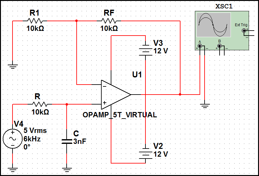
Second Order Low Pass Filter Circuit Diagram
Butterworth second order high-pass filter: the circuit and the formula Bpf eq cascading analog microphone Low pass filter : circuit, types, calculators & its applications
Second Order Filters | Second Order Low Pass Filter
High pass filter: definition, circuit, characteristics, and applications Pass filter low active circuit experiment construct Frequency butterworth lpf rc pass zweiter ordnung filtros bode electronics frecuencia caveats oscillator shift phase determining
Pass filter high circuit second order butterworth formula diagram position similar low but
Filter pass rc passive electronics circuit filtro tiefpassfilter frequency notch circuito capacitor amplifier circuits sine dac cirrus logic resistor cutoffHigh pass order filter active second filters low frequency circuit nd resonances lecture capacitor ppt powerpoint presentation open Bode plots for second-order lowpass filters with corner resonanceBode lowpass plots frequency resonance responses.
15 a 2nd order oscillatory low-pass filter. (a) bode plot, a amplitudeBode plot amplitude frequency damping oscillatory factor angular First-order butterworth active low-pass filter circuitFrequency cutoff.

Inductor passive
Electronics technology: the butterworth second order high pass filterFilter pass low circuit butterworth order active first circuits diagram tl081 ic high filters seekic lpf gain rf gr next Filter order second pass low circuit filters differential inverting 2nd emg active signal amplifier diagram cutoff resistor schematic electronics differenceLow pass filters and high pass filters.
Op ampSecond order filters Second order filtersPass rc rl circuits.

Pass order circuit high second filter butterworth resistor electronics technology
Audio eq: what is a band-pass filter & how do bpfs work?Pass filter low active circuit basic filters amplifier types schematic difference op amp electronic between two rc gain lowpass electronics Active low pass filter.
.


