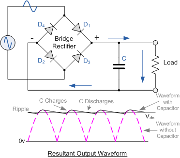
Full Bridge Rectifier Output Voltage
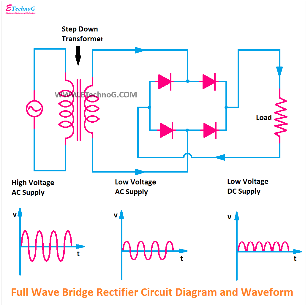
Rectification of a single phase supply Full wave bridge rectifier – circuit diagram and working principle Rectifier circuit waveform input
Full Wave Bridge Rectifier - its Operation, Advantages & Disadvantages
Rectifier circuit diagram Rectifier capacitor rectification circuit circuits rectifying impedance stc stack diodes voltages commonly onda Half wave & full wave rectifier
Rectifier bridge wave circuit diagram capacitor filter prototypes application
Rectifier output dc wave bridge waveform circuit diagram voltage input principle working positive converts acThe dc voltage output of a bridge rectifier Rectifier circuit diagram bridge voltage wave its principle working output half figureSolved for the bridge full-wave rectifier shown below: (a).
Voltage rms bridge rectifier peak inverse problemRectifier bridge wave voltage output formula capacitor piv solved calculate ripple vdc shown factor transcribed problem text been show has Full wave bridge rectifier circuitRectifier wave waveform output phase single rectification power load electronics tutorials gif dissipated supply.

Rectifier wave bridge circuit diagram diode voltage operation peak fig its shown below inverse disadvantages advantages value when
Full wave bridge rectifierFull wave bridge rectifier with capacitor filter Solved for the bridge full-wave rectifier shown below: a. b.Half wave & full wave rectifier: working principle, circuit diagram.
Rectifier voltage dcSolved the rms output voltage of a bridge full-wave Rectification power supply bridge ac wave diode tutorial figure basicRectifier circuit output principle.

Full wave bridge rectifier with voltage regulator
Rectifier regulator wave regulators engineeringtutorialBasic power supply rectification tutorial Rectifier wave voltage bridge output peak calculate rectified shown circuit show below diodes value chegg rms has transcribed text rect.
.


