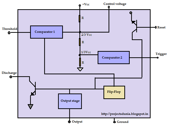
Block Diagram Of 555 Timer
555 timer diagram internal schematic ic circuit block types applications application Timer internal 555 timer ic
Introduction to the 555 Timer - Circuit Basics
555 timer ic: introduction, working and pin configuration 555 timer ic diagram block astable multivibrator circuit using internal Astable multivibrator using 555 timer
How does ne555 timer circuit works
The 555 timer ic555 timer diagram ic block basic circuit complete circuits op guide flip tutorial two flop has projects collection 555 timer led flasherTimer graham lambert.
555 timer diagram chip ic block transistor tutorial discharge output multivibrator circuit does logic electronics flip flop monostable bistable mode555 timer – a complete basic guide 555 timer and 555 timer workingExplain the functional block diagram of timer ic555.

555 timer diagram ic block basic complete circuit circuits guide op tutorial flip two has flop collection
555 timer ic-block diagram-working-pin out configuration-data sheetDancing light using 555 timer Timer ic diagram block introduction working configuration555 timer – a complete basic guide.
555 timer ic block diagram digital applications circuits functional covered additional category pages will555 timer math 555 timer working electrical4u diagram internal blockIntroduction to the 555 timer.

Ece: 555 timer
555 timer circuit using light dancing circuits diagram chip pcb easyeda 555timer pulse ne555 projects lm555 time astable cloud software555 timer ic 555 ic timer diagram circuit astable description delay pinout pins block using multivibrator time ic555 internal functional explain ground circuits555 diagram block timer ic led flasher electronics wikitechy.
Timer diagram block figure math555 timer ic diagram internal block wikipedia ne555 flip flop transistor Timer pinout block555 timer tutorial.

Timer 555 circuit diagram schematic ne555 datasheet pinout discrete kit does block circuits transistor works eleccircuit integrated connection functional pins
555 timer diagram ic block circuit ne555 controller configuration op working pins flip flop pwm discharge electrical resistive .
.


