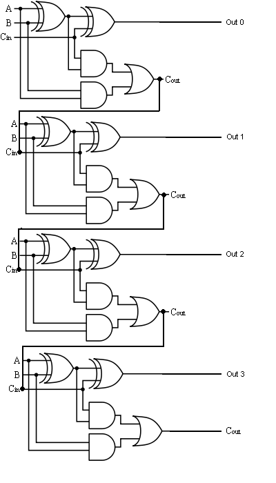
4 Bit Full Adder Schematic
The answer is 42!!: four bit full adder tutorial Adder bit using circuit adders four half circuits implementation watson just single box into outputs latech edu Download 4 bit adder circuit stick and logic diagram
The Answer is 42!!: Four Bit Full Adder Tutorial
Logic diagram of 4 bit full adder Adder circuit diagram schematic bit works figure Adder bit using layout gate figure transmission efficient
Digital logic design: full adder circuit
Adder logic multiplexer lookahead vhdl4 bit binary incrementer Adder bit circuit three binary schematic using diagram solvedEfficient layout design of 4-bit full adder using transmission gate.
Full-adder circuit, the schematic diagram and how it works – deeptronicMultisim adder 4 bit full adder (1)Binary circuit output geeksforgeeks incremented.

Inf2c-cs lab 2: systemc basics
Adder bit four logic gates byte 4bit nand boolean not nor values possible possibilities hold answer trick function known createSolved design a three-bit adder circuit using half-adder and Adder circuit logic using digital boolean implementation diagram implement functionAdder bit ripple carry schematic fa lab ac cs code makefile inf courses labs ed teaching.
.


